Ohinemuri Regional History Journal 43, September 1999
[no author given - E]
This article outlines the method of working the Talisman mine during the years of peak production, 1910 - 1914. By that time the mine had been working for 16 years and considerable development work had been carried out and ore reserves known.
BACKGROUND
The Talisman Mine was situated on Mt. Karangahake and in 1893 there were four men at work on the Talisman claim owned by A Shepherd and others. They found that capital was needed to develop the mine and an attempt was made to raise it on the London market. This failed and so a small local company was formed and registered on 5 November 1894.
Five and a half tons of ore were sent to Germany for treatment in 1893, and in 1894, 280 tons treated at the Crown Mines Battery. This gave a good return, but the Crown Mine Company wanted the Talisman to pay all treatment costs plus 20% of the bullion, and they would not allow the Talisman to have the tailings. These terms were unacceptable and so the Talisman decided to build its own battery. The first, of 10 stampers was in operation by 1895 but it was unsatisfactory. Little ore was crushed until 1897 by which time the battery had been remodelled.
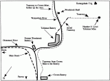
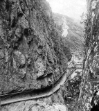
At first the mining, all on the Maria Reef, was confined to the upper levels of the Karangahake Mountain. After commencing the No. 8 Level in 1900, a shaft, eventually 1000 ft deep, was sunk from a chamber. Lower levels were driven from the shaft and from the Woodstock Company's stopes. The Woodstock was taken over in 1904, and after enlarging the Woodstock shaft, access to the very deep levels could also be reached by walking up the tramline alongside the Waitawheta River, entering the Woodstock No. 5 Level (river level), and descending by cage in the Woodstock shaft to the Talisman No. 14 Level. There were only two more levels below No. 14 and these were reached by ladder. The Talisman shaft from No. 8 Level (half way up the mountain), did not have a cage to lower men, only an ore skip and ladder ways.
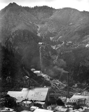
General view of the area of the Karangahake Mt. that was mined by the Talisman Coy. Talisman battery and the power houses are shown. The top of the aerial ropeway is in the upper centre at the level of the No. 8 Level. Photo 1909.
Talisman Mine - Karangahake
Ohinemuri Regional History Journal 43, September 1999
By 1905 the Talisman had increased from the original 30 acres to 506 acres by taking over the Bonanza Claim (1896), the Talisman Extended, Royal Mail, Victor-Waihou, and finally Woodstock in 1904. These companies had, in many cases, already merged or taken over still other claims; Diamond, Rose, Maria, Ivanhoe, Sir Walter Scott, Truro, Kenilworth, Hidden Treasure, just to list a few. The first dividend, $60,000, was paid out in 1906.
Between 1906 and 1914, extensive mining was carried out between No 8 and No 13 Levels. These were good years for the company, which in 1912 employed 360 men. Production had climbed steadily from 4194 tons in 1898 to 13,396 tons in 1902, then jumped to 47,267 tons in 1903. The peak was reached in 1914 with 52,210 tons of ore mined. There were a few setbacks, mainly by way of flooding in the lower levels, especially in 1909 when the nearby Crown Mine Company stopped pumping for a time, but on the whole, good progress was made and returns were satisfactory.
Within a few years the end was to come. Development work in 1913 proved disappointing. A crosscut from No.11 to the Welcome Reef failed to find payable ore, neither did crosscuts put out from No. 13 Level in 1914. It was hoped to locate other reefs parallel to the main reef, but none were found.
During 1919 bores were sunk from the lower levels, Government drills being used. These bores were sunk on various angles in an endeavour to locate payable ore. Zinc, iron, sulphide and black flint were found, but all attempts to find payable ore by prospecting, mining and drilling failed, and operations ceased by the end of December 1919. An attempt to salvage rails and air pipes was made, but the pumps failed and water rose in the lower levels. In 1920 the Company went into liquidation. During its life time the Company produced most of the 3,510,691 ozs of bullion, which came from the claim. The bullion was valued at £2,958,013 and the Talisman Consolidated Company paid £1,150,972 in dividends. In 1912 each ton of ore cost about £2.3.4 to mine and treat. Actual mining was 12/9 per ton, milling was 13/1 per ton, and development costs (finding the ore), 9/9 per ton. The balance was office expenses 2/1 and construction, 5/8.
The Company's personnel included:
|
General Managers |
Mr Mitchell and Mr H Stanfield |
|
Mine Managers |
Goldsworthy, McCombie, Rickard, Dutton |
|
Battery Managers |
Taylor, Phillip, Dean |
|
Smelting Foreman |
Gwilliam, Dette, Carpenter |
|
Assayers |
George Chappell, Metcalf |
|
Office |
Mr Kitching |
|
Metallurgist |
D Dean |
WORKING THE MINE
The general history related above gives a broad outline of the mining activities. By 1910 mining operations were largely confined to the Maria Reef, the largest on the goldfield.
ACCESS
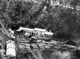
No. 8 Level Talisman Mine. Buildings include blacksmith's and carpenter's workshops and change and cook houses. The timber will be used underground. Tramway on left to aerial ropeway. Road access from Mt Road on the right. (1913)
Talisman Mine - Karangahake
Ohinemuri Regional History Journal 43, September 1999
In considering the ways used to reach parts of the reef being worked, it is necessary to realise that this company operated independently from the Woodstock Company until after 1904.
No. 8 Level Talisman Mine. Buildings include blacksmith's and carpenter's workshops and change and cook houses. The timber will be used underground. Tramway on left to aerial ropeway. Road access from Mt Road on the right. (1913)
In the upper part of the mountain, the reef was reached by adits driven through the side of the mountain. The levels were numbered downwards, the highest, which was 380 feet below the summit, being No. 1. As the levels were progressively opened up it was necessary to drive crosscuts of increasing length through the Woodstock Company's ground before reaching the reef in their own claim. At No. 8 Level the crosscut was more than 1000 feet long. It was therefore decided, that to obtain access to the lower levels, a shaft would be sunk from a chamber cut in the No. 8 Level.
Until 1898 the lowest level to be worked was the No. 7 Level, and although a start was made on the No. 8 crosscut in 1901, most of the 150 men working at the time were employed at the upper levels. A great deal of stoping was carried out in the upper levels as the ore was rich. Part of the upper section of the reef was within the Crown Mines ground and to work the southern portion of the reef that lay within their own ground, the Talisman Company drove the No. 4 Level through the Crown Mines portion and, after reaching their southern boundary, the reef was again picked up and stoping resumed.
In 1902 the No. 8 crosscut was in 1000 feet and by 1903 had reached the reef that was payable for a width of 4 to 16 feet. Because of the good ore found, vigorous development work took place. A chamber was cut in the No. 8 Level and the sinking of a shaft commenced. This shaft dipped to the west, 62 degrees from horizontal and pitched slightly to the south. The westward dip enabled the shaft to follow the reef, although in the very deep levels the reef's westward swing was so great that crosscuts had to be put out from the shaft to reach it.
From No. 8 Level to No. 11, the shaft had two quartz ways and one ladder way. Below No. 11 a fourth compartment was added for a mullock skip; the dimension of the shaft was then 18 ft x 6 ft. By then the Talisman had taken over the Woodstock mine and could make full use of their workings that were on the same reef. Mullock was only hauled to the No. 11 Level and then tipped out at river level. Later these lower levels were reached from the Woodstock shaft, which, like the Talisman shaft, was sunk from a chamber in the mountain, but here the drive was just above the river level in the Waitawheta Gorge. Originally it was necessary for the men to climb down ladders in the Talisman shaft, but later the main access was to walk up the tramway in the Waitawheta Gorge, descend by cage in the Woodstock shaft and then walk along No. 14 Level. The Talisman shaft was eventually 1000 feet deep, the bottom being 560 feet below river level.
SYSTEM OF DEVELOPMENT
After commencing the Talisman shaft the system of development was to open up a drive, 8 feet by 5½ feet, each 200 feet sunk down the shaft measured along the dip. In payable areas, connections were established by rising and sinking winzes at intervals of 100 feet to 150 feet along the drives. Intermediate levels were put in to avoid stoping unpayable areas.
Waitawheta Gorge. Entrance to Woodstock shaft. Boiler House supplied steam for the pump in the Woodstock shaft. (1913)
Overhand stoping was used, the men standing upon broken country rock obtained from development work or from abandoned stopes in the upper levels. Any mullock obtained from, say No. 13 Level, was hoisted by the mullock skip to a hopper at No. 11 Level from which it was drawn for filling in the stopes between No. 11 and No. 12 Levels. At times special mullock rises were put up into the hanging wall of the reefs to obtain filling. These mullock rises were driven at a grade sufficient for the material excavated to run down into the stope. A grade of about 50 degrees was found the most satisfactory. These mullock rises were of about 9 feet and 12 feet and the contractors were paid (1911) 25 shillings per cubic foot. The price included distributing the rock in the stopes. The rises were sometimes up to 80 feet in height. This was an expensive way of obtaining filling, although such rises occasionally proved useful in testing branch veins.
Rock drilling in stopes was done by machines, as far as possible. The machine in use (1911) was the Improved No. 2 National made by Taylor Horsfield of Bendigo, Victoria. The piston on these machines was 3 inches in diameter with a 5-inch stroke, giving approximately 400 strokes per minute. They were driven by compressed air and the men would object if the pressure was less than 70 lb per square inch as it made drilling difficult. Eighty pounds pressure was the normal working pressure. The machine weighed 300 lb and the support columns varied from 2'6" to 11'6" long, with a screw bar at one end. During boring, a water jet was employed, the water being taken from the rising pump, giving water at 130 to 140 lb per square inch. In blasting, Nobel's gelignite, blue jacket fuse and No. 6 detonators were used.
HAULAGE AND WINDING
The mine trucks had a capacity of 16 cubic feet and ran on rails with a 18-inch gauge. To ensure easy running one wheel ran loose on the axle and the opposite wheel was fixed, one free wheel being on the right-hand side and the other on the left. In the lower levels ore and mullock pockets were used, from which hoisting was done in skips.
The broken rock was tipped from the mine trucks between rails, directly into the hoppers. To prevent large lumps from going through, a bar was secured between the rails and the large lumps were broken by hammer.
The ore hoppers were of about 75 tons capacity and the mullock hoppers of 20 tons. The average load of an ore skip was 28.5 cubic feet and, for a mullock skip, 15.5 cubic feet. These skips rested on rails set at a 2-foot 5 inch gauge in the inclined shaft. The Talisman shaft winding engine was placed in No. 11 Level and this was driven by compressed air. It had two cylinders, 12 inches diameter by 15 inches stroke. The drum was 3 foot 6 inches in diameter and the rope, 1 inch in diameter. A good average lift for a 8-hour shift was 150 tons from the hoppers on No. 12 and 13 Levels to the No. 8 Level, where the ore was trucked by a contractor to the aerial tram terminus outside the mine. The trucks of 21 cubic foot capacity ran on rails with a 2-foot 5 inch gauge, and were pulled by a horse. Another contractor dispatched the ore to the battery by the aerial tram. A skip load was 12 hundred weight of ore. The aerial tramway was on a grade of 18 degrees and up to 40 tons per hour could be sent down to the battery.
POWER
The first battery was driven by water power. By 1902 two Babcock/Wilcox boilers had been installed to drive a Wheelock Corliss single cylinder steam engine of 245 HP. The mine inspectors report of 1902 states that the breakers and stampers were operated by steam power and the concentrators, pumps, etc., by water power.
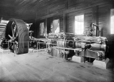
The 560 HP steam engine which drove most of the Battery machinery. The concrete foundation, driving arms and wheel shaft can be seen at the present time. Photo 1909.
In 1906 an Ingersoll Sergeant compound air compressor was installed in the old Woodstock Battery buildings to supply air for underground pumps. The small compressor previously used for this purpose was unable to cope with the demands as the mine expanded and went deeper.
Power requirements at the mine's peak years (1910/14) were considerable.
Water power - A dam in the Ohinemuri River supplied water, via a 1800 foot long pipe of 4-foot diameter, to a 18-foot 6 inch Pelton wheel that provided 320 HP. There was a fall of 80 feet between the dam and the Pelton wheel. A dam in the Waitawheta River supplied water to drive two Victor turbines that drove dynamos. This dam also supplied water used in the treatment process. About 9 tons of water was used to treat one ton of ore.
Steam Power - There were four Babcock/Wilcox boilers fitted with mechanical stokers. The coal used was Huntly brown coal, which was found satisfactory. Steam from the boilers was supplied to the engine by a 660-foot long pipe. The engine was a compound - tandem Corliss engine of 560 HP, built by Messrs Fraser and Chalmers. (See photo on page11) The cylinders were 18 inches and 34 inches in diameter with a 42-inch stroke. It ran at 72 rpm. The boilers also supplied steam to a Riedler air compressor having a capacity of 3100 cubic feet per minute and to an Ingersoll Rand compressor with a capacity of 3700 cubic feet per minute. These two compressors supplied the air at a pressure of 100lb per square inch. The Ingersoll compressor installed in 1906 was also in use, being driven by water power from the Ohinemuri River Dam. This supplied 1250 cubic feet of air at 90 lb per square inch. There was also a Union Iron Works machine giving 600 cubic feet of air at 40 lb pressure.
To drive the Cornish pump installed in the Woodstock shaft, there was a Babcock/Wilcox Boiler driving the pump engine, also a Corliss compound engine of about 500 HP. This boiler and engine were built near the shaft in the Waitawheta Gorge. (See photo on page 10)
With the exception of the Cornish pump, all other pumps and winding gear below ground level were driven by compressed air. From the compressors the air went to a balancing cylinder at the No. 8 Level and it was then distributed throughout the mine. The pipe from the compressors to the receivers at No. 8 Level was 8 inches in diameter and at a pressure of 90 to 100 lb per square inch. A maximum of up to 3500 cubic feet of air was used per minute in the mine to drive the drills. Four men were continuously on the job repairing and checking the great length of pipes in use, which wound their way along the various levels and up and down shafts and rises to the working faces in the stopes. By the time the air reached No. 16 Level, it had travelled through more than 5000 feet of pipes.
DRAINAGE
The levels had a rise of 9 inches per 100 feet and most of the upper levels could drain naturally, which was one of the advantages of mining in steep country. Surface water was picked up in the No. 7 Level and was used to drive a smithy blower at the blacksmith work shop at the entrance to No. 8 Level.
For drainage below river level, pumps were installed in the bottom of the Talisman shaft. These could handle 41,000 gallons per hour which was adequate as the average flow was around 25,000 to 30,000 gallons per hour at the time. However, when the nearby Crown mine's pumps stopped, the flow of water became excessive and in August 1908 the No. 13 Level became flooded. To be certain of being able to handle any amount of water that could be expected as the mine went deeper, it was decided to install a large pump in the Woodstock shaft. It was also proposed to sink this shaft deeper, keeping ahead of the rest on the mine's development, and thereby keeping the workings dry.
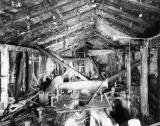
All the pumps were driven by compressed air except the Cornish pump installed in the Woodstock shaft. This pump could handle 124,000 gallons per hour. It was driven by a Corliss engine supplied from steam boilers situated in the Waitawheta Gorge. The pump spur flywheel was 17 feet 6 inches in diameter and weighed 43 tons and the balance bob weighed 40 tons. (See remains of pump in photo on page 13)
Later, after No. 14 Level was driven, a pump of 1,000 gallons per minute capacity was also installed in the Talisman shaft. As various winzes were sunk at the deeper levels of 15 and 16, it was necessary to install smaller pumps in the winzes.
In 1918 when a bore was sunk in the Woodstock section, water pressure of 100 lbs per square inch was struck. This gives some idea of the problems of working the lower levels.
VENTILATION
This was mostly natural with the air current entering at the river level and after being directed down to lower levels by doors in No. 11 and 12 Levels, it rose up the Talisman shaft. The compressed air being used at the working faces also helped. In November 1910 the temperature in the north end of No. 13 Level was recorded at 70o F and at the south end, 75o F.
LABOUR
The contract system was used as much as possible. One contractor who usually had from 6 to 12 partners, would be responsible for the whole of the mining and exploration on his level, with the exception of the timbering for shoot and leading stopes. This work was done by timbermen paid by the company. The contractor obtained his steel, dynamite, candles, etc. from the company and the cost of these, plus drill sharpening, repairs and breakages were deducted from his account. The contractor delivered the ore to the ore hopper on his level and the tonnage was estimated by counting the number of skips handled from his level to No. 8 Level. Payment was made on this tonnage, which was checked by the number of truckloads taken out by the horse tram to the aerial ropeway.
In driving, rising or sinking payment was made per foot of progress or, if the material was ore, then payment could be made on the tonnage as described above. The filling of stopes was done by the same contractor. Extra payment would be made for sets of timbers in drives and winzes.
The number of men underground was between 180 and 200 men during the peak years. In the battery, between 8 and 13 men were employed.
SAMPLING AND MINE PLANS
Very careful plans were made as work proceeded, including assay plans in plane and longitudinal section. Each stope was also recorded in detail with the assay results. Samples for assaying were continuously being taken from the working faces.
EXCAVATION OF THE WOODSTOCK PUMPING CHAMBER
Woodstock Shaft chamber, late 1960s. Note the remains of the pump. The person in the centre, background gives an idea of the scale. Section of Woodstock Pump Chamber, showing method of excavation. The timbers would not have been in position at the stage of excavation shown.
To accommodate the pump capstan, new winding engine and pump engine, the chamber at the head of the Woodstock shaft had to be enlarged to 100 feet in length, 40 feet wide and 25 feet high. Because of the dangerous nature of the rocks, the whole of the drilling was done by hand.
First, a drive was extended the full length of the proposed chamber and this was met by a crosscut driven in from the river level. A stope was then put up and widened until the height of the proposed chamber roof was reached. Sufficient broken rock was always left in the stope for the men to stand on and reach the roof. Excess rock was trucked away. The working space was reached by an inclined rise. Before the chamber was completely excavated, the roof rafters were put in position. These heavy timbers were pulled up the rise by a hand winch And could be handled much more easily by the men standing on top of the broken rock than if the chamber had been completely excavated first. After the rafters were in place the broken rock was removed and the sides excavated back.
GLOSSARY
An explanation of some terms used in the article, "Talisman Mine"
|
Adit |
A tunnel driven horizontally from the surface. |
|
Assay |
The process of ascertaining the value of gold and silver in the ore. |
|
Battery |
The name given to the treatment plant. (Derived from a battery of stampers.) |
|
Crosscut |
A tunnel driven to reach a reef or cutting across the reef system. |
|
Drive |
A horizontal tunnel on the reef. |
|
Driving |
The term used to describe the process of tunnelling. |
|
Level |
The name given to the various horizontal drives. (tunnels) |
|
Mullock |
Waste rock not containing minerals worth processing. |
|
Ore |
That part of the mineral deposit which contained sufficient minerals, such as gold and silver, to be worth processing. |
|
Rise |
A small section shaft formed by working upwards from a level. |
|
Skips |
The containers in which the ore or mullock was brought up the shafts to the surface. |
|
Stampers |
Part of the machinery used to crush the ore at the battery. |
|
Stope |
The excavation from which the ore was extracted. |
|
Stoping |
The process of extracting ore from a stope. |
|
Tailings |
The discarded portion of the ore after treatment. Usually ground very finely. |
|
Winze |
A small section shaft sunk from a level. |

